top of page




ELECTRICAL
DC/AC Inverter Technology
Complexity: High
DC to AC Inverters
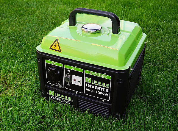
The term inverter is used in the name of many electrical products on the market - similarly to eco, silent, green, etc - as the newest marketing strategy, starting the list from the high power welding machines through the newest washing machines up to the electric generators - see picture below - powered by internal combustion engines, and what is more, everyone knows that inverters are the heart of solar cell systems as well.
In this article, I will only deal with general-purpose single-phase portable inverter devices that can produce - in different qualities - AC 230 voltage from a DC power source, such as a battery.
In the following sections, I would like to show a little more detail about the grouping, structure, and operation of these devices, just in my kitchen electronic language, because I deal with this nice hobby subject only out of self-diligence, since I also have several kinds of inverters, which I have had to fix a few times.
First of all, let me say that the internal structure and operation of high power DC-AC inverters are mostly quite complex, and on the top of that these electrical devices operate in particularly dangerous voltage ranges. Therefore, I consider it extremely important to emphasize that the maintenance of inverters requires serious and reliable expertise and without it no one should try to fix them. So, if an inverter fails, it can only be repaired by a qualified specialist.
Of course, if you do not have an appropriate qualification in the field of electronics, always call a specialist! Before I move on, I would like to emphasize that it is strictly forbidden to carry out any electrical installation or reparation without confident knowledge and proper qualification!
Classification of Inverters
Even portable inverters can be excellent additional power sources in the event of the main 230V AC network power failure, however, it is important to clarify that certain non-negligible factors must be taken into account, because three inverter types can be distinguished according to the quality of their output signal, which are namely the square wave, trapezoidal and pure sine wave categories, and their price also rises in that order.
If something starts like this then I think it's already easy to figure out that the application-circle of simpler inverters is very limited in the practice, as the quality of their output 230V AC signal greatly affects their usability, and here we have already touched on the point.
So, before choosing an inverter, we need to know what type of consumer we are going to use with it, and here not only the nominal energy consumption is the main factor, but let’s look further that what may be exactly the crucial details on such an issue.

One of the main reasons for this is that the output waveform of the cheapest inverters is usually a simple and rough square wave which is far from the pure sine wave. However, in the quasi-sinusoidal inverters - which can form actually the mid-range category - the waveform is like a trapezoid, and the peak value is adjusted to 325V as in the case of the standard 230V AC sine wave - since √2 * 230V = 325V - but the quasi-sinusoidal inverters have a relatively large dead time when their output is 0V, and this dead time is adjusted so that their effective value should be - in the better case and not as in the picture below - finally 230V. So those are one - or rather more - degrees better than a square wave, but still not a pure sine wave.

However, I would like to emphasize the fact that with sufficiently fast switching and much more serious filtering, the desired sine wave can be approached very nicely, and not to mention that thanks to the PWM, even a nicer output can be produced than the standard 230V (± 10%) AC sine wave, which can also fluctuate rather unevenly - see picture below - in the practice.

Of course, the pure sine wave inverters are in the best category, but they are quite expensive. Not to mention the more sophisticated portable solar inverters - see picture below - that also have their own built-in MPPT or PWM charging module, and even handle external aggregator power through automatic switching to provide a continuous 230V to consumers.
So that I already mentioned the cost ranges, let me also note that it is also possible to make a much cheaper pure sine wave inverter at home too, as there are already very nice sine wave inverter drive modules on the market, but that will not be the subject of this article now.

Anyway, why is the quality of the output signal so important?
I consider it useful to know that we can distinguish the consumers from an electrical point of view so that the given consumer may fall basically into the ohmic - like a traditional light bulb - inductive - like an electric motor - and capacitive categories such as capacitor circuits.
The internal structure of purely ohmic consumers is obviously very simple, and other electrical consumers are mostly quite complex, in which almost everything can be found, starting the list from simple resistance through capacitors to transformers. I think so, it is enough to take off the cover of a completely ordinary electrical device - which seems pretty simple from the outside - to be a little surprised at how many tiny colored parts can it actually contain. So that is why such devices are a bit more complex inductive and capacitive consumers at the same time.

Before I move on I almost forgot to present a great purely inductive example that came just in time, because - as I mentioned above - the electric motor itself is also an inductive consumer, for which my dad’s faulty angle grinder is a very good example that I’m fixing right now.
Anyway, I find it interesting to note here that the energy produced and fed back by the electric motors - after switching them off - in generator mode cannot be used advantageously by the electronics of the inverters, but it will turn into a harmful heat load and dissipates on the output elements of the inverter electronics.
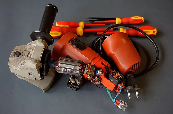
Let's go further into slightly deeper waters. So, from a purely theoretical point of view, the point is that the impedance and resistance of ohmic consumers can be considered quite constant if the temperature change is ignored. In other words, there is no phase shift between the voltage and current components in these consumers, and in this sense, these are the simplest and most grateful electrical consumers because they are not sensitive at all.
The other two passive elements are already slightly more complex. So, from a physical point of view, the coil and capacitor are already energy storage components for which it is important what the drive signal looks like. Moreover, the impedance of inductive consumers increases with increasing frequency - so the current is delayed relative to the voltage - in the case of AC, but in the case of DC, coils can only show a normal resistance.
However, the capacitors show a completely opposite operation compared to the coils, because the impedance of capacitive consumers decreases with increasing frequency - so the voltage is delayed relative to the current - in the case of AC, but in the case of DC, they can only show an open, i.e. infinite resistance.
So far, let's say it's okay, but how does all this relate to the output signal of the inverters?
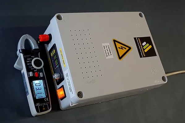
Then let's start with the worst-case since the most common square wave inverters have serious problems with capacitive loads because the suddenly steep voltage changes will generate large current pulses - which means undesired heat load - on the side of capacitive consumers, and not to mention that these rough square signs also increase the heat load of inductive consumers. Therefore, it makes more sense to use these square wave inverters only for ohmic consumers and in my experience, it is not worth trying anything else to prevent undesired damages, but I think the following surprising measurement tells everything without words as it shows 53Hz and 252.5V at the output of a simple square wave inverter in no-load condition.

As I mentioned above the output waveforms of quasi-sinusoidal inverters can only approach the pure sine wave with finer and multi-stage waveforms, and thus their output voltage consists of not so nicely rounded switching signals. I experienced pretty quickly with the first inverter that if the output voltage of the inverter consists of less fine switching signals - i.e. the more angular the sine signal - then it will generate smaller or even larger pulses with opposite voltage at the inductive loads which in response - i.e. as an unpleasant back effect - can easily damage the inverter switching devices.
Based on my experience the quasi sine signs can not cause particular problems for transformers
and brushed electric motors, apart from the fact that their heat load increases slightly, and they have different noises during operation.
Last but not least the proper estimated power sizing is perhaps the biggest problem with pure sinusoidal inverters since even an electric motor - as an inductive consumer - can easily absorb many times its rated power especially in the start-up phase, which also depends greatly on the load torque. The portable solar inverter already shown above is therefore not really suitable for such difficult tasks as it has only 2kW of continuous power and 4kW of peak power.

Moreover, it is also worth noting here that for consumers with larger electrolytic capacitors, the discharged capacitor consumes much more current at start-up - since the energy is stored in the dielectric - to reach its operating voltage, and therefore it must be charged first with 230V AC before starting, which means a serious sudden overload for inverters. Anyway, if we pay more attention to current fluctuations, the initial peak current can be more easily noticed even when starting a more serious 450W switched mode power supply, since such a device can suddenly absorb quite easily up to 7-800W of power in the start-up phase.
In addition to this, I think almost everyone knows that synchronous motors with auxiliary and starting capacitors are at the top of this chain, and on top of all that, not to mention those not-so-rare cases, when they are starting with high load torques.
However, let’s not go that far because my dad’s little 600 W angle grinder shown above - with a perfectly repaired microswitch - also requires more than 1500W of starting power, and it’s just a tiny single-phase bronze brushed motor without a soft starter.

Therefore these non-negligible factors need to be carefully considered to avoid the unpleasant surprises, even before buying sinusoidal inverters, in which case the main rule is that the higher the continuous output power, the more widely it can be used. Thus, the more muscular 24V inverter shown in the picture below can start a 1 kW synchronous motor with 3kW continuous and 6kw peak power much more confidently.

Transformers as central components
I think it is worth noting here some basic thoughts about transformers as well.
Inverters producing alternating voltage from direct voltage, so for this reason transformers are used here in reverse mode compared to power supplies, because now the supplied DC voltage must be converted back to AC voltage.
In the case of transformers, the size of the core always depends on the power to be transmitted,
and at low frequencies the transformer core made of soft iron plates is sufficient, but at higher frequencies the core made of ferrite is already required.
The low frequency soft iron core transformers are much larger in size - their losses are also higher - than the high frequency ferrite core transformers. In addition to their differences in size, it may also be a telltale sign that the high frequency ferrite core transformers usually have lemon-yellow plastic foil insulation, which already shows that they are not scaled to 50Hz.
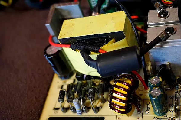
Perhaps the most conventional inverter solutions use a fairly large and heavy low frequency soft iron core transformer, which usually has two separate secondary coils with center tap for 2 input voltage, such as 230V / 2x12V, where the two secondary coils will be in this case the two semi-primary coils, and thus, the 12V PWM pulses generated by the MOSFETs - I will show in detail its usual operation later - are connected to these coils in the opposite phase, and the magnitude of the secondary voltage - as the desired output voltage - can be set by the fill factor of the PWM signal.
The more serious inverters use one or more - depending on the desired performance - much smaller, but high power and high frequency ferrite core transformers that are connected in parallel. In such inverters first, the 12V DC voltage is transformed - with the help of switching mode - to about 320V at a high frequency, and then a rectified DC voltage is generated using a rectifier bridge circuit, and then this 320V DC voltage is interrupted by an H-bridge circuit consisting of 4 corresponding high power MOSFETs which produces finally the 50Hz output with the help of switching mode. I will illustrate this method in a little more detail below.
Anyway, if the transformer is not centrally tapped but it has two separate secondary windings with same output parameters, then the two coils can still be combined, but the output wires must be chosen so that the direction of winding must be taken into account.

What about Content and Operation?
Here, I'm not going to analyze a given circuit with exact values, but I would like to illustrate in a well-structured and thematic way the most interesting individual circuit components and their possible role.
So, inverters usually consist of two large main blocks, where the first stage is a DC/DC converter and the second stage is actually the DC/AC converter, where these DC/DC and DC/AC stages are galvanically isolated from each other for safety reasons. What could be - based on my opinion - the most typical electrical components of an inverter beyond the transformer already shown?
Let’s start with the first high-current switch stage that handles the huge current flowing from the battery and move on nicely in line.
First, let me start with the most basic component, because against reverse polarity, it is worth putting a properly sized diode - in the company of some fuses - on the input side. Then the first major component can be an input filter block connected in parallel with the battery, which can consist of electrolytic capacitors with a capacity of a few thousand uF.
In parallel, there can be a small ceramic or tantalum capacitor as well, which is actually a decoupling capacitor. Anyway these small mostly nice colorful tantalum or ceramic decoupling capacitors are often used directly next to ICs and switching transistors as well, and in all circuits where electrical noise - for example due to frequent relay switching - is a common factor, because the noise is a fast-changing, random signal and that can be filtered out using these small bypass capacitors, which are actually grounding capacitors. So no matter if the input voltage drops or increases because using the decoupling capacitors, the ICs will eventually get a nice even supply voltage in all conditions.
I only highlight them because they are easily recognizable even to those as well who are less familiar with electronics, and they also play a pretty important role in inverters, which I think it's good to know, but let's move on.

It is well known fact that the pure constant DC voltage can not be transformed so for this reason
the first main task for inverter electronics is to interrupt frequently the 12V DC voltage supplied from the battery with dense switchings, since it must be transformed to around 320V which is the peak value of the standard 230V AC.
This high frequency 12V DC interruption is performed by MOSFET semiconductors, which are also fairly easily recognizable components, and many of them can be seen in solar inverters and switching mode power supplies, but of course we can find them in many other electronic devices as well.

So, usually in inverters at least 2-2 FETs - because FETs can work very efficiently in H-bridge topology - next to the transformer are connected in parallel, and these are controlled by the PWM control board in the company of 2-2 smaller switching transistors, and this way these output signals from FETs will drive the main transformer at a few tens of kHz.
Thus, a high-frequency PWM signal sequence enters the primary side of the transformer, which is a series of 0V and 12V constant signals at a given frequency due to the mentioned very fast switchings.
It is very important to emphasize here that since FETs operate in switching mode, their heat load is therefore relatively low. Moreover, FETs are much better choice than transistors, since they are voltage - and not current - controlled semiconductors.
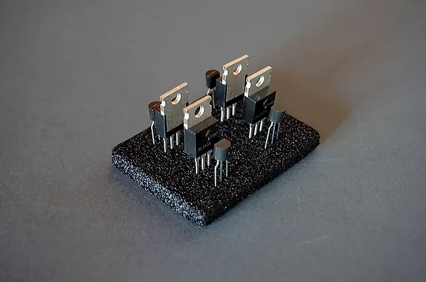
So far it is clear that the high frequency 12V DC interruption is performed by FETs, but for this operation FET driver ICs are also needed to switch the FETs when operating at high frequencies.
For this purpose in higher quality single phase inverters usually an additional smaller printed circuit board - inverter driver module - includes this PWM control circuit - along with overload protection and other extra features - and we will see later that in the last step the high power IGBT transistors - which will form the 50Hz 230V AC high current output - are also controlled from here. This is the brain and this is the key to what control signals will drive an inverter.
So in the best case, if the given inverter has a more sophisticated pure sine wave inverter driver board, then this application specific integrated circuit includes the program that generates a fairly accurate PWM signal for the two half-periods separately, and thus all that is required is to output the control signal to one PWM output in one half-period and to the other in the other half-period for switching FETs.
Are there other simpler solutions to it? Of course yes.
So what is the simplest inverter drive circuit? At this point I have to mention that the central element of inverter control circuits can even be in the most simplest case, an infinitely simple, one-piece astable multivibrator circuit, such as the most basic - see picture below - 555 timer IC, instead of the much more sophisticated microcontrollers mentioned above.
This astable multivibrator IC directly generates a frequency of 50 Hz, and two separate FETs are driven with opposite signal status generated by this simple timer IC for the low frequency soft iron core transformer as I mentioned in the transformers section.
Such and similar inverter technologies have an extremely simple construction, but of course the quality of their output signal is also very poor. Therefore, I think that is enough of them and let us return to the general solution and structure.

In summary so far it is clear that the drive signal for the FETs is provided by a separate circuit
controlled by a dedicated PWM control IC - in the better case by microcontrollers - which has an integrated internal oscillator for this purpose, whose operating frequency can be fixed - by its input parameters - typically at a few tens of kHz with a properly sized timing capacitor and timing resistor connected to the corresponding input pins of this PWM control IC.
This will generate the PWM square signals in the positive and negative ranges which are isolated from each other, and are essential for generating alternating voltage in push-pull configuration mode.
Such more serious inverters use high frequency pulse transformers, and converting the 12V DC voltage at a high PWM frequency - as already described above - to around 320V, then rectifies this using a Graetz-bridge in the company of a suitably sized 400V electrolyte filter capacitor.
This capacitor stores the 320V DC voltage converted so far, so this DC voltage is regulated, and this way the inverter can keep the 230V output rated voltage even under varying loads.
This is the point where the first stage ends, which is actually a DC/DC converter.
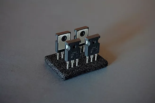
The second stage of the inverter is actually a DC/AC converter, where this boosted 320V DC will be converted by the inverter drive module - using a separate oscillator circuit for this purpose - to 230V 50Hz AC effective output using an H-bridge consisting of at least 4 high power MOSFETs or IGBT - see picture below - transistors, where the characteristic colorful Zener diodes will acts as a protector of a feedback voltage from the transformer.
Then in the last step the LC filter - consists inductor (L) and capacitor (C) - will finally shape the voltage from the H-bridge to a much nicer 230V AC sine wave, if we are dealing with some more serious inverter.
The inverter under repair - shown in the picture below - is only trapezoidal, and does not have filter inductor at its output, but the 2-2 IGBT transistors after the Greatz bridge, which form the mentioned H-bridge circuit, are each 500V 20A transistors, and it's easy to see that the 50Hz 230V AC output is coming out of here. Anyway, the TO-247 packaging of the IGBT transistors can already indicate in itself the high performance. Moreover, at first glance, it is quite clear that it has a high-frequency ferrite core transformer, and can only operate at high frequencies.

The inductor itself is a crucial passive component in inverters as well, since it can significantly reduce the high-frequency interference, and also filters out the inductive spikes returning from the transformer. Anyway, an inductor stores energy in the form of a magnetic field, because the magnetic field induces a voltage on the coil due to current changes.
Moreover, it is also worth knowing that the inductor and the capacitor are frequency-dependent resistors in the AC circuit, so that as the frequency increases, the resistance of the inductor increases, but the resistance of the capacitor decreases. Therefore the capacitor opposes the voltage change and the inductor opposes the current change, and therefore the capacitor is used as DC insulator, and the inductor is used as DC conductor.
So all in all the capacitor is a complementary partner of the coil because it provides DC isolation, so only the AC component can pass through it, and thus, for example, only the AC component can go to the transformer by it in the inverter electronics.

Thank You for reading this article.
bottom of page