top of page


MECHANICAL
Vehicle Diagnostics
Opening Thoughts on OBD Diagnostics
The OBD DTC scan tool can be a standalone device or just an interface, which can be connected easily to the Diagnostic Link Connector (DLC) of the vehicle, but only from that quick step is not worth thinking that everything will be solved by erasing the Diagnostic Trouble Codes from the PCM memory. Moreover, I would like to indicate at the beginning that reading some OBD DTCs may not always clearly identify the exact reason of the problem either. In addition to this, simply reading and clearing OBD DTCs usually seems to be a very simple and convenient task, but it is actually a bit more complex issue than it seems at first glance. Of course, my opinion is that if you do not have an appropriate qualification in this field, always call a specialist!
The On-Board Diagnostics - as a self-diagnostic software - in vehicles is basically responsible for emission standards, and in the case of failures, this software will lit the well-known yellow Check Engine Malfunction Indicator Lamp (MIL) on the instrument panel right at the moment the DTCs set by the software in the EEPROM, which means an Electrically Erasable Programmable Read Only Memory.

The diagnostics itself is an examination process, which can usually be connected to different kinds of measurements. This type of vehicle diagnostics - through the OBD interface - is briefly called by engineers as serial diagnostics, which indicates the data connection between the PC serial port and the PCM controller data line, where the communication takes place through the K / L line or CAN bus. I think so, it is worth knowing about these that the K-line is bidirectional and the L-line allows only one-way communication, and I will show the CAN bus communication more in detail a little below.
First of all, it is important to know what communication protocol will be required for successful OBD scanning, which could be for example:
- ISO 9141 K / L line,
- SAE-J1850 VPW,
- SAE-J1850 PWM,
- CAN ISO 11898-2,
- CAN ISO 11898-3,
- ISO 15765-4 / SAE J2480.
It is a well known fact that various OBD scan tools are already quite cheap and available on the market, but the cheaper OBD readers may be able to read or even clear some PCM related DTCs - for me that is far from enough - to some degree, but of course, they will not be able to handle other systems. Furthermore, one of the most important things would be to read all the live data as well, of course, if supported by the given device or interface.
I want to emphasize this because at this point there can be serious misunderstandings about expectations, especially for more expensive devices, which are worth clarifying before buying.
Moreover, I also want to highlight here that there are some - just seems to know everything - fairly expensive OBD scan tools - either as a standalone device with own display or just a simple interface - on the market that support all the communication protocols and can read PCM related error codes and live data as well, and in addition to these they can perform some reset functions for some brands too, but in fact they are completely incapable of communicating with different control modules other than PCM, and of course they are not able to perform any configuration and actuation neither.
So, I think it's clear that the most appropriate OBD scanner - for universal tasks - knows all the basic communication protocols, and - more importantly - the manufacturer's specific protocols.
In order to make this topic completely clear it is worth knowing that the PCM unit is responsible for the complete control of the engine from the charging system to transmission and emission control. This large control unit is often located under the hood in a fairly protected area, often around the battery box, and always the thickest wiring harness is connected to it because it can communicate with all sensors and other electrical control units in this lead role.
So, the well-known Powertrain Control Module (PCM) is the main control unit of the vehicle,
but as I mentioned, there are several other electrical system control modules as well, such as:
- EBCM as Electronic Brake Control Module,
- TCM as Transmission Control Module,
- SCM as Suspension Control Module,
- EPS as Electric Power Steering,
- LCM as Light Control Module,
- DCM as Door Control Module,
- BCM as Body Control Module,
- climate control system,
- electric window lift,
- and so on.
So it would be really beneficial if they were also handled by the OBD DTC scan tool, which is not such a simple matter, because such devices are usually very expensive.
Anyway, I did not manage to find the perfect solution in the universal category, which is one of the main reasons why I do not want to highlight different types and brands.

About CAN in my kitchen language
The OBD abbreviation means simply the On-Board Diagnostics, and the CAN abbreviation means the Controller Area Network, which is a communication standard - basically it is also obsolete -
which allows all the electrical control units in the vehicle to communicate with each other via the common data bus - the bus is the communication circuit - using a given communication protocol.
So, I can say that almost everything in the latest and about 10 years old vehicles is controlled by the CAN network from the electric window lift to all kinds of sensors, even the brake lights too.
That is the main reason why I do not prefer too much the limited - even if it is CAN compatible - OBD scan tools, which can not communicate with the EBCM, SRS, SCM, EPS, DCM, or climate control system, and can not send basic actuation commands to the vehicle. In other words, it is important to me that my OBD scan tool should not be just a one-way diagnostic device, which cannot send system self-check requests to different control modules.
Those who are enthusiastic as hobby specialists on this subject will certainly know that, mainly for safety reasons, even several CAN bus networks - mostly with different abilities - have been operating in parallel in most vehicles for a long time. It is well-known that basically 3 types of CAN are used in the automotive industry depends on the speed of communication. The low-speed CAN can transmit information at a speed of about 10 kbit/s, so it can only control very low-priority devices such as the electric window lift. The medium-speed CAN can transmit information at a speed of about 100 kbit/s, and is already able to control more complex devices such as the climate control system. The high-speed CAN can transmit information at a speed of about 1 Mbit/s, and it can already control very high-priority devices such as the PCM, TCM, BCM, SRS, and EBCM.
Anyway, to make it even clearer, I would like to point out that even the high-speed CAN is not very beneficial for the transmission of more serious media content. Of course, there are other brand-specific communication systems that significantly exceed the capabilities of CAN, but CAN has been the most widespread technology for almost 20 years, from the commerce category to premium vehicles. However, I would like to emphasize once again that with the development of technology we are talking about a very limited communication network.

In my opinion, in connection with DTC reading via OBD diagnostic, it is worth knowing that the failure codes related to the CAN communication are typically the U-codes. Of course, there are additional classes as well because the P-codes are associated with the powertrain, which belongs to the engine and transmission, and last but not least the B-type refers to the body - better said chassis - such as an airbag.
Moreover, the DTCs can also be classified, as the first group contains the higher priority DTCs,
which immediately lit the MIL lamp, and the software immediately stores the freeze frames data about them, but there are lower priority failures that do not turn on the MIL lamp immediately,
but if the failure was repeated several times it will eventually turn on the MIL lamp, but it is also true that in certain cases the MIL lamp may turn off under certain conditions as well. Of course, it’s a lot more complicated than I've shown in a few sentences, but the point is maybe in there.

Parallel or Peripheral Diagnostics
I think this type of diagnostics is eventually the most essential part of the vehicle repair process since if I want to go deeper than just read the failure codes, it is worth considering the possible indirect fault reasons as well, before starting the repair process in the wrong direction.
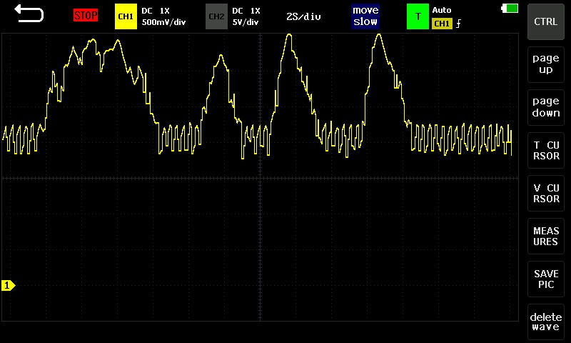
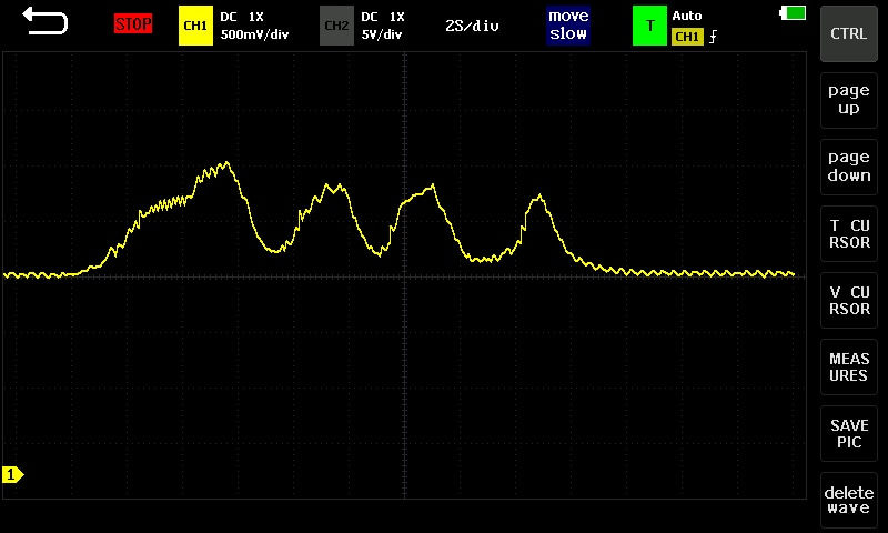
This more complex step will already require other specific measuring devices as well - such as a smart multimeter, or a more serious oscilloscope, or even an oil pressure or engine compression gauge - which are, of course, significant parts of parallel or peripheral diagnostic tasks.

In order to identify the real cause of a given failure - if the serial OBD diagnostic can not clearly indicate that - it is usually advisable to check the vehicle component that appears to be defective or the input and output signals of the suspicious sensors - of course during dynamic operation and over the entire range - before just quickly replacing them, which can easily be a completely unnecessary and costly step.

This branch of parallel diagnostics already requires significantly more mechanical knowledge and deeper experience in the field of analog and digital electronics. To make this short section even more understandable, the gallery below shows some of my recent vehicle electrical-related test measurements, which will be analyzed in more detail in later articles in connection with various sensors or even PWM-controlled inductive components as well.

2

4

7

2
1/4
Anyway, a very good example of more complex debugging processes is the well-known lambda sensor failure - of course, it could even be listed further as well - which can be stored indirectly for many other reasons, which are not directly the faults of the oxygen sensor.

Thank You for reading this article!
bottom of page