top of page


MECHANICAL
MAF sensor
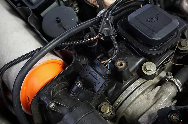
Mass Air Flow (MAF) sensor
The main purpose of the MAF sensor is to send accurate input signals to the Powertrain Control Module for the dynamically changing - rich or lean - air-fuel mixture calculations.
The MAF sensor measures in general the flow rate - at least its absolute value - of the intake air volume, and its temperature with the help of an additional NTC thermistor.
I would like to emphasize here that these parameters are necessary to measure the air mass at a given cross-section with a good approximation. It has become quite common and natural by now that the latest hot film type MAF sensors are already able to directly measure much more accurately the volume and pressure of the intake air including the positive or negative sign or even the humidity of the air flow.
So the dynamically changing amount of intake air mass can be calculated very accurately so that
if we know the cross section of the intake pipe, the temperature, pressure and flow rate - with its sign - parameters, in other words the pulsation - due to the movement of the pistons - of the intake air.
Yes, this is a great - one more thing that can easily get dirty and go wrong - sensor, but this was not the general solution not even in the recent past.
By the way these few sentences were not a too small step in the automotive industry, because previously it was only possible to indirectly calculate the estimated value of the mass of intake air. Let's just say this solution was enough - especially for me - too, since even my 2005 petrol engine doesn’t even have such a dedicated sensor, despite the fact that not only turbocharged engines may include a MAF sensor.

So now to be more serious, there are basically two categories of MAF sensors on the market, the hot wire and hot film type.
Both are heated - as their name suggests - to a certain degree above the ambient temperature in order to perform their main function. Basically their operation is quite simple because with the flow of intake air - at much colder temperatures - the hot foil or hot wire cools back to a certain degree, and consequently a few milliamps more current - which is already an easily measurable factor - will be required to keep the sensor at the specified operating temperature.
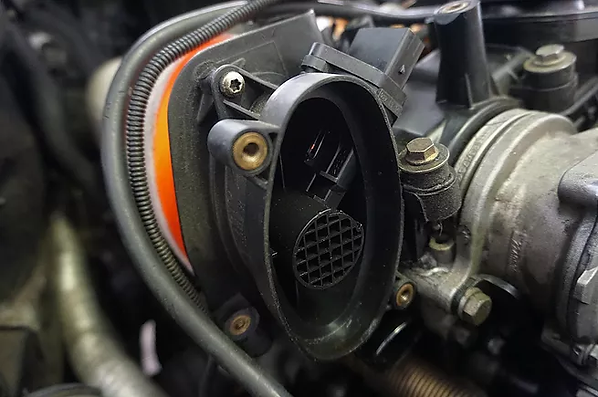
In terms of its internal structure the hot-wire MAF sensor has two heated wires, one providing an isolated reference setpoint, and the other measuring the cooling degree of the air flow. It is not a big science, but I know that this sensor can also be very expensive for some vehicle types.

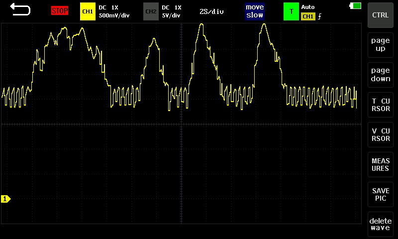
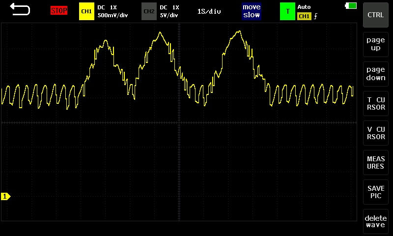
As shown in the image gallery below, the hot-wire type MAF sensor has an analog output - in other words varying voltage output - which can only take values from the usual 0 and 5 V closed interval according to the current airflow rate, while the hot film type MAF sensor may even have a digital frequency controlled - Pulse Frequency Modulated (PFM) - signal output, where the low frequency output belongs to the low air volume, and the higher frequency output belongs to the higher air volume.
The hot film type MAF sensor - as I have already referred to it at the beginning - represents a more sensitive and much more serious technology, which is able to sense very accurately the pulsation of the dynamically changing airflow.

2

4

5

2
1/4
Why is this so useful?
Why is it useful to know the exact amount and behavior of the intake air?
So in short, the intake air volume of petrol engines - and also of more modern diesel engines - is controlled by a choke mechanism - whereas it is well known that there is a butterfly valve in the throttle body housing for this purpose - and the Powertrain Control Module has to regulate the amount of fuel to be injected according to the mass of the intake air, and so the engine can run more economically, of course only as long as this sensor is pretty clean.

I would point out here that nowadays the mass of the injected fuel is calculated according to the mass of the intake air and not in the opposite direction. See my measurement below for more details.

By the way, would the regulation work in the opposite direction?
It is worth mentioning that in the case of conventional intake diesel engines there is no built-in throttle body housing with butterfly valve, and they do not have MAF sensor either, whereas the maximum air volume can be drawn in continuously through the intake manifold, and the engine speed and thus the power output are controlled by the mechanically driven diesel dosing unit, which is a professional invention in all respects.
So the answer is yes because originally the throttle regulation of diesel engines did not work at all with the principle of the choke control mechanism. However, I can say that the throttle body, along with the MAF and MAP sensors, appeared in turbo diesel engines in the early 2000s, which were still equipped with an electronically controlled and mechanically driven diesel dosing unit, as shown in the rather exceptional figure below.

Typical MAF sensor failures
The lower output signal of the MAF sensor will, of course, result in a lean fuel mixture. In this rather common case the cold start of the vehicle is not perfect and the engine may hesitate under load. In this case, it is advisable to disassemble and carefully clean the sensor and its housing.
Then check the 12 V supply voltage provided by the engine control unit to warm up the sensor, and if it has a built-in NTC thermistor, its 5 V supply voltage should also be checked on the electrical connector.
Then an oscilloscope can be used to perform much deeper analysis to measure the analog or digital output voltage signals. Finally, let's just say that this sensor alone cannot cause e.g. a completely impossible engine start, since it is not a setpoint sensor like a crankshaft dead center sensor.
bottom of page
