

ELECTRICAL
DRZ Regulator Upgrade
Complexity: Medium
Suzuki DRZ400 S as perfect base
If you follow my blog regularly, you will soon notice that one of the favorite topics in my articles spins around the Suzuki DRZ400 S motorcycle. Of course, besides this subject, I'm facing all sorts of interesting technical challenges without selection, but in this article, I will focus only on this family member.
I like this vehicle because if I just want to refuel at the gas station 10 km away from home, then this original plan could easily turn into an instant 400 km international tour, of course, without any food, drink, proper clothing, or another preparation processes. Many times I get home late at night, many times it rained, many times I got lost because I don't use navigation either, but I had a lot of beautiful experiences.

So I decided to build the best adventure motorcycle in the dual-sport category that fits my vision perfectly. I could talk a lot about what the term adventure means in the motorcycle categories, but now, I will approach this subject from my own aspect. In my opinion, the Suzuki DRZ 400 S is an excellent base for this challenging project. Anyway, it is not a negligible factor in the equation either, that according to my estimation, this vision would be feasible without too much effort and financial investment.
The first challenge began when I wanted to install some electrical accessories, such as heated grips and auxiliary lights. Of course, I knew that due to the capabilities and structure of this motorcycle, the capacity of the OEM voltage regulator is strongly limited.
So the main problem arose right at the beginning of the whole project as soon as I checked the technical specification. This fact was not particularly surprising to me due to the small dimensions of the OEM voltage regulator, the design of the passive cooling surface, and not least because of its outdated technological solution. In summary, my first step was to find enough robust and completely reliable solutions to this issue.

The OEM Suzuki Regulator
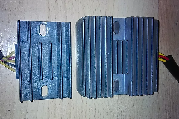
I haven't disassembled this OEM - it's a little expensive for that purpose - voltage regulator yet, but it is only a traditional diode based rectifier. I often felt my OEM regulator quite hot even under normal conditions because this is one of the features of this outdated electronic solution, and its cooling surface is slightly small, as I referred to it above.
The excessive heat congestion of a conventional diode-based voltage regulator is not surprising to me either, as 0.7 V falls in the opening direction on every single diode, which, depending on the current flow, must be dissipated. It is also worth mentioning that MOSFET solutions have much lower internal resistance and a much lower heat loss because the less voltage drop results in less heat loss in the voltage regulator by default.
Let’s go a little deeper and try to quantify the parameters from the perspective of the electronic system. As shown in the technical description in the specification, the maximum rated power of the OEM generator is around 200 W.
Considering the electrical consumers on the motorcycle, I would say that the maximum load on the OEM regulator can be between 150 and 180 W and nothing more. Of course, this is just my estimation, based on earlier experiences, since I have designed and built some voltage regulator circuits, plus considering the estimated maximum possible cooling capacity of this component.
In summary, the OEM regulator is a relatively weak link in the whole chain, which is completely understandable due to the protection of the much more expensive and complicated generator and, of course, thanks to the more marketable technology in the 2000s.
Anyway, the generator itself with its 200 W is not a power plant either, but it was also surprising that other brands have even smaller generators in this motorcycle category.

The Electrex Regulator
My bridging solution was the Electrex RR17 voltage regulator, which is already a MOSFET-based much more advanced technology. The abbreviation means the Metal-Oxide-Semiconductor Field-Effect Transistor, which is essentially a voltage-controlled transistor. As far as I can see, the most popular building components right now are the high-performance IGBT transistors and MOSFETs in electronics. MOSFETs are also used as switches and power amplifiers, and what is more, MOSFETs require a similar operating point setting as bipolar transistors. I like to use them in power electronics circuits, so I always keep a few dozen MOSFETs of the most common types on the shelf.

As I mentioned above, the MOSFET technology is better because it produces much less heat than conventional diode-based voltage regulators. Not to mention that it has a larger cooling surface and is about 3 times heavier than an OEM voltage regulator, and it has built-in thermal protection in comparison with the diode-based solution. So the Electrex RR17 works much better where the airflow is limited, and its rated load capacity is around 300 W, which is a special pleasure for me.
The only difficulty was the different connectors, which I will deal with in more detail a little below, but this was not a particularly stressful challenge for me.

What about the alternator?
Let me say a few words about the generator what I see from its structure. The Suzuki DRZ 400 S has a claw-pole permanent magnetic alternator. So there is no excitation current in this generator design because the permanent magnetic flywheel excites the generator coils.
It consists of 3 pieces of 3-phase star point windings, which are shifted relative to each other by 120 degrees. This component is called officially generator stator, and at 5000 rpm between the three Y1-Y2-Y3 phases, I measured 75-75-80 V alternating voltage at no load, which is completely acceptable.
As I can see, one of the coils, which I just call now a lonely coil, from which the black and white wires come out and like the other coils it also has 48 threads is a special excitation coil that sends a positive signal wave to the CDI for the appropriate spark. For the perfect spark, this little excitation coil is not negligible on which column it is on, as it has a dedicated location.
Of course, due to this lonely coil and the geometry of the 3 phase design, the coil numbers will be 6-5, 6-5, and 6-6 between the phases. That’s why I can measure 75-75-80 V between phases at 5000 1/min, and of course, the voltage level is directly proportional to the engine speed.
The black magnetic sensor outside the flywheel is the well-known pickup coil, which can detect the rotational speed and thus provide signal output with a varying pulse to the CDI unit.
Technical parameters:
Copper wire diameter: 0.80 mm.
The number of turns: 48 on each coil.
Maximum rated power: 200 W at 5000 rpm.
The internal resistance of windings: 0.5 - 1.25 Ohm.
The idle voltage between the phases at 5000 rpm: 75V-75V-80V.

Installing the Electrex regulator
This project required only a minimal correction because the sockets of the new regulator were not exactly the same as at the OEM. I used the original Japanese sockets for the new RR17 regulator.
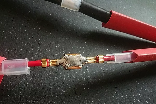
To replace the mentioned sockets, I carefully crimped new high-quality copper cable terminals to connect each wire. During pressing, I had to be careful not to damage the cross-section of the copper cables because of the unexpected current transmission loss.
Due to the oxidation resistance, it is important to use suitable watertight connectors in automotive electronics. In my opinion, always the original Japanese sockets are the best and no matter how old they are exactly.

After checking the crimping quality, I also soldered the common connection point of the copper cable terminals. Here I eliminated the possibility of an unexpected connection failure too.

Testing the new Regulator
The purpose of the voltage regulator in vehicles is to keep the system voltage at about 14.0 V in every case.
After installation, I performed some more serious load tests, and the result was 100% satisfactory without exception.
In my opinion, a healthy degree of charging voltage should be between 13.8 - 14.3 V after the voltage regulator under all circumstances.
Anyway, I've used more than 300 operating hours so far, and it just works well.

My short opinion is that this new 300 W Electrex regulator completely meets my expectations.
The good news is that I've never felt it warm so far. As you can see, it has large heat sinks on both sides, and thus even the minimal heat generated can be dissipated easily and quickly to protect the electronics.
