top of page



MECHANICAL
Hydraulic workshop press
Complexity: Low
Opening Thoughts
In my opinion, a mechanic workshop without a high-performance hydraulic workshop press is like a car without wheels. It is really an essential tool because a simple task such as bearing replacement often requires high compressive forces.
If we go a little deeper, the running gear of vehicles can only be replaced with the help of a reliable hydraulic press. In addition to all this, it can be used for many other things, such as straightening heavy steel profiles or other similar corrections.
In this little article, I will present what aspects I considered and how I made my super strong workshop press.

Let's get started
My first most important task was to select the strongest hydraulic jack since the design of the frame structure is highly dependent on the maximum compressive force.
Originally, I intended to adapt my 15-ton hydraulic lift to this project, but over time I found a much more serious hydraulic unit for this purpose. A little lower - when assembling the frame structure - the picture will also show the differences between the two hydraulic devices.

Of course, I quickly disassembled the hydraulic jack dedicated to this project because I want to get a reliable and practical workshop tool in the final result. Telling the truth, it was a tough challenge to disassemble this industrial-sized hydraulic equipment, but it was worth fighting with the elemental forces.
In the next step, it is worth checking the seals as the device will be used upside down, just like in factory solutions. Keep in mind that the pump must be able to suck hydraulic oil in reverse position, so for this reason minimal modification will be required inside the lift.
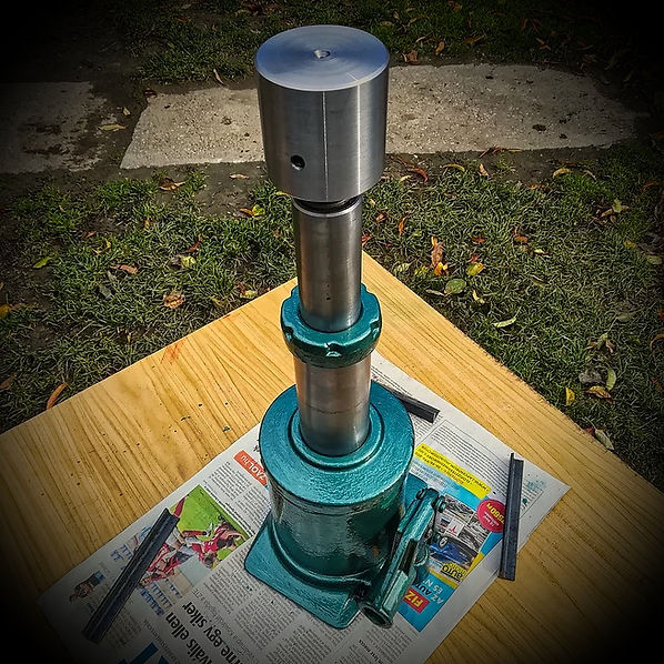
I chose a yellow copper pipe with a precision of hundredth mm for the suction valve of the pump. Despite the tight fit, I even used a Loctite 242 thread locker to avoid unexpected leaks, which is the blue liquid around the copper tube shown in the picture.
It is definitely advisable to use an oil-resistant sealing for this minimal modification because it is not an easy challenge to disassemble such a robust hydraulic jack. I waited a few hours for the glue to dry completely and then pressure tested the system several times.
I disassembled the dual-piston system and gently polished the pistons, and then I lubricated the super clean seals with silicone grease before the whole assembly. These jacks are usually filled with HLP-32 hydraulic oil for very fine use, so I don't think it's worth filling them with a stronger viscosity oil.

It is important to note that these sensitive parts should only be laid on soft and clean clothing, as even the slightest damage can be catastrophic. Keep in mind that seals must be able to withstand a few hundred bar pressure perfectly during roughly ten tonnes of pressing. I almost forgot to say that I used brake cleaning fluid for cleaning, as more serious nitro-based cleaners are out of the question here.
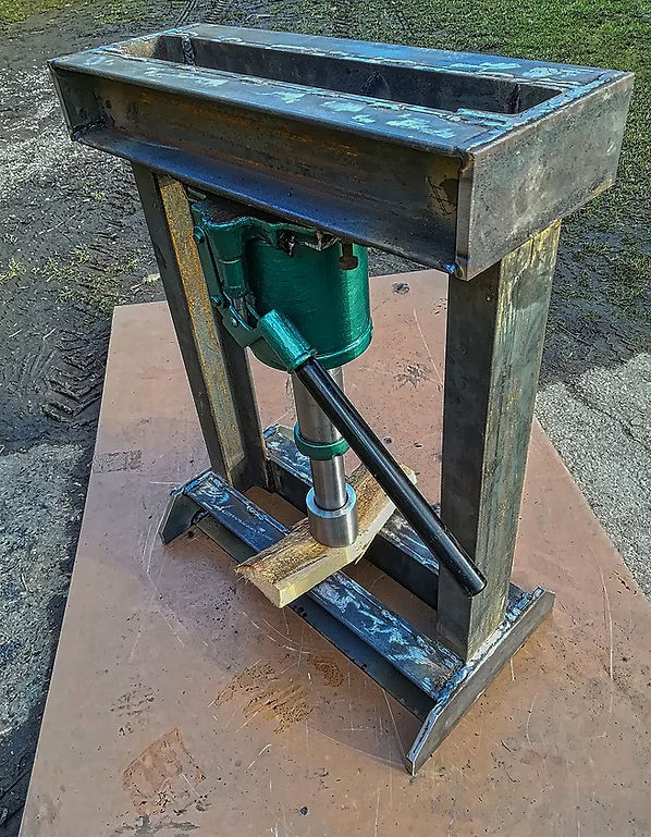
After complete assembly and external surface preparation, I beautifully repainted the hydraulic unit with several coats of hammer varnish.
As the peak point of this renovation process, a special CrMo stainless steel piston was made with a cross-section of 70 mm for the safe transmission of the gigantic compressive forces, since such a material quality can be used in industrial conditions.
After all this, I was able to design the exact dimensions and material of the frame structure.
Of course, the longitudinal and diagonal frame elements consist of robust hot-rolled 80 mm U steel beam profiles.
These are high-quality structural steels with enough high tensile strength which - according to my calculations - meet my expectations. In addition, to make the structure super strong, each diagonal U-beam also received an extra 80x10x500 mm flat steel reinforcement.
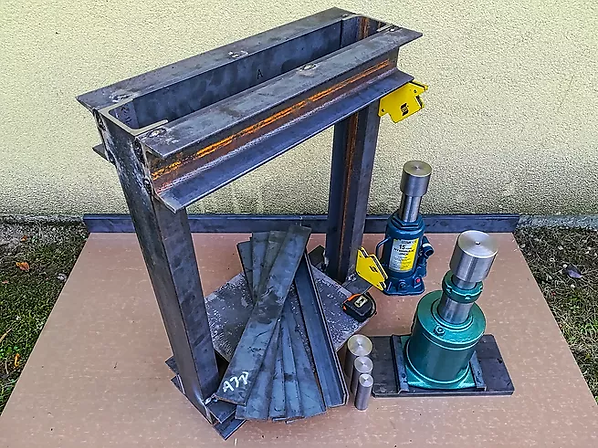
Nothing should be left to chance, so for that reason, the hydraulic unit fits into the mainframe structure via an enough robust 15 mm thick 300 x 170 mm solid metal plate. The design of this mounting bracket requested some creativity and the precise welding of the components required a great deal of patience and consideration.

Originally, I wanted to screw it all together with 16-20 mm screws with a tensile strength of 10.9, but instead, the entire structure was welded together with about 80 pieces of 2.5 mm coated ESAB electrodes.

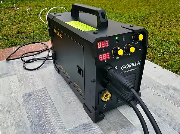
In connection with this project, I started to make a closer friendship with the welding machine presented earlier. So far, I'm satisfied with this choice. In fact, it has 2 times as much power as I can use for my own projects.
MMA (Manual Metal Arc) and finer FCAW (Flux-Cored Arc Welding) functions were used during the whole work process.
Unfortunately, I can’t measure its final weight, but I’m sure I got a real heavyweight device because I can’t move my workshop press alone anymore. The first pressing test was really convincing, and it seems to me that I'm closing a very successful project this time as well.
Thank You for reading this article!
bottom of page